The basic chassis consists of some nice plywood (which will be disassembled and stained after everything works) for the bottom and sides, as suggested by the Experimental TV Society plans. The top is two pieces of Plexiglas.
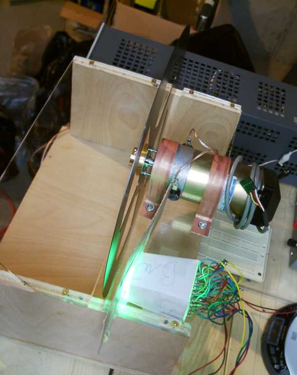
In this view you can see the motor and its mounting straps, the disk, hub, and some of the mounting screws, and the temporary cardboard light concentrator taped to the LED array (also temporarily taped to the chassis).
The motor includes a tachometer pulse generator on the end, which I will not use. This assembly is fastened on in such a way as to make it difficult to remove without damage, so I am leaving it in place. In order to do this, I reversed the top pieces from the ETVS plans, using the short piece in the rear to mount the motor, leaving the tachometer hanging out in the rear. The mounting straps are soft metal pipe straps found at the hardware store. They just happen to be copper plated.
The LED array consists of red, green and blue LEDs on 0.1 inch center perf board. Each LED is inserted in the plain side and soldered to the isolated copper lands of each hole along with a ballast resistor that connects to another series LED. The free connections are then connect to flying wire busses that go to the power FET driver. Two blue LEDs in series was the maximum possible with a 12 volt supply, and it was easiest to simply follow the same wiring pattern for green and red. Obviously, an expressly patterned board would make this easier, but I had no facility to make custom boards.
The brass mounting hub was turned and its center hole drilled by the same friend who supplied the motor. He also made a boss on the disk mounting side to fit the 3/4 inch disk center hole. This means that the disk was automatically centered, and made it especially easy for me to drill the mounting holes for #4/40 hardware. I used a small drill press to make the holes, with placement determined by scribing the mounting hole locations of the purchased scanning disc. He also flatted the hub in two places to make it easy to drill setscrew holes, which we then tapped for #4 screws.
![]() Back to Mechanical TV Progress
Back to Mechanical TV Progress