Loop Characteristics
Frequency lock in the Synchronization Loop Model occurs when dC(n)/dn = dC'(n)/dn. If the loop filter F(z) is an all zeros filter (a good choice for F(z) is a unity gain moving window averaging filter having N taps each of value 1/N), then we have a 1st order loop. Such a loop will achieve frequency lock with a non zero phase difference C(n) - C'(n). This fixed phase difference after frequency lock can be reduced to 0 if we use a second order loop (F(z) with a pole at z = 1). However it is hard to maintain stability in such a loop. Small differences between the actual loop parameters and the design loop parameters can easily push the poles of H(z) outside the unit circle causing instability. A first order loop is very stable and an all zeros filter with many taps is easily implemented by a microprocessor. The fixed phase difference after frequency lock does increase the required receiver buffer size.
Unlike a first order phase-locked loop, the first order STC loop will pull in from any offset frequency to any transmitted frequency within the range of the crystal VCO, because of the integrating effect of the STC counter. The loop parameters do affect the final phase (STC value) error, the speed of pull-in, and the jitter response.
Phase Difference After Lockup For First Order Loop
A first order loop will achieve frequency lock with a fixed phase difference between the encoder STC counter and the decoder STC counter. The worst case frequency difference between the encoder STC and the decoder VCXO center frequency is 1620 Hz (either may be at 27 MHz +/- 810 Hz). The decoder VCXO should be specified to have a midpoint frequency with this range. At a 10 Hz sampling rate,
![]()
counts per sample maximum between encoder STC and decoder VCXO center frequency.
The largest fixed phase difference (difference between the received PCR values and the local VCXO counter) after lockup for this first order loop will be
![]()
Simulated Lock Up Time and Phase Difference
The closed loop transfer function for the first order loop is
![]()
For unity gain 128 tap averaging filter (N = 128),
![]()
and the loop transfer function is
![]()
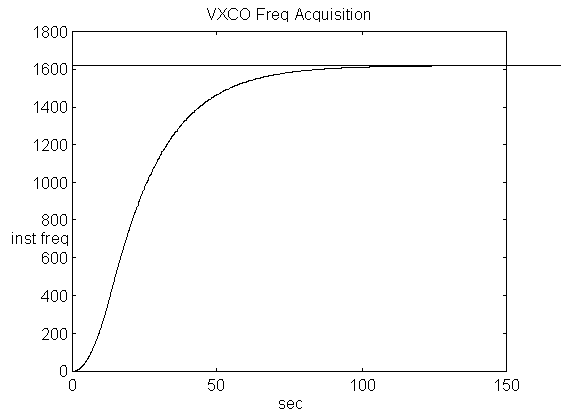
To determine the frequency acquisition time for this loop, C(n) and C'(n) are initially zero, and C(n) is set to a ramp sequence increasing at a rate of 162 counts per sample. This represents the worst case 1620 Hz initial difference between the encoder and decoder clocks. With the above transfer function, the sequence C'(n) can be calculated. Decoder instantaneous oscillator frequency in counts/sec is 10(dC'(n)/dn). This is plotted below with respect to n/10 (n = # of samples, 10 samples/sec). The figure below shows that lock occurs after about 130 seconds.
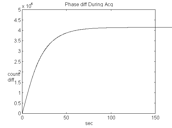
Phase difference = C(n) - C'(n) is plotted below with respect to n/10 (n = # of samples, 10 samples/sec). It is seen that phase difference after lockup is about 41000. This closely matches the predicted phase difference
![]()
Simulated Jitter Response
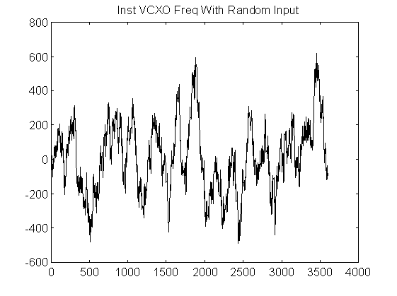
We assume a locked steady state condition to test the effect of jitter. The input sequence C(n) is set to be a random sequence with a uniform distribution from -108000 to +108000 representing a +/- 4ms jitter. Then sequence C'(n) is calculated using the loop transfer function. The instantaneous VCXO frequency is calculated in counts/sec as 10(dC'(n)/dn) and plotted versus n (n = # of samples, 10 samples/sec). Note that perfect jitter immunity would be represented as C'(n) = 0,0,0..., so that dC'(n)/dn would also = 0,0,0......
The figure below shows a decoder VCXO frequency stability of about +/- 22 ppm for a +/- 4 ms jitter in PCR arrival times.
Previous: Synchronization Loop Model
Next: Decoder Buffer Requirements
Up to Decoder STC Synchronization