Synchronization Loop Model
The basic synchronizer consists of a first order feedback loop. Each incoming PCR is subtracted from the receiver STC counter, and the filtered difference (times a proportionality constant) is the control voltage for a crystal VCO. This loop stabilizes with the correct frequency, but with an offset in STC that is proportional to the offset in frequency between the encoder 27 Mhz oscillator and decoder 27 MHz oscillator free-running frequency. This implies that the decoder should have a slightly larger buffer to absorb the offset timing.
Difference signal filtering is needed to reduce unnecessary response to PCR arrival time jitter. Jitter reduction must be traded for settling rate. MPEG sets a tolerance on input PCR jitter. The output jitter that is tolerable depends on the application, for example the use of the 27 MHz clock to generate display pixel, horizontal, and vertical clocks. If the recovered 27 MHz clock is used to generate NTSC color subcarrier, more stringent requirements with respect to both jitter and settling rate may need to be met.
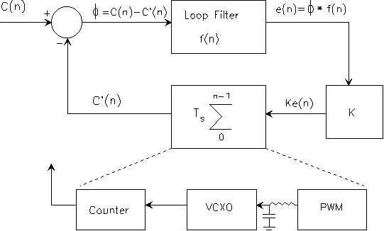
The feedback loop in the receiver can be modeled as a sampled phase locked loop. The loop compares each value of a local STC counter sequence C'(n), driven by the receiver VCXO, to a sequence of received samples of the encoder's counter C(n), driven by the encoder STC, where for both counters we interpret


The * symbol in the e(n) calculation denotes convolution. C(n) represents PCR samples that are assumed to arrive at a 10 Hz rate. In this model the 27 MHz component of both the encoder and decoder clocks has been factored out of the sequences C(n) and C'(n). In other words C(n) and C'(n) are referenced to 27 MHz. Therefore the reception of an unjittered 27 MHz STC is represented by C(n) = 0,0,0,0......... If C'(n) is frequency locked to an unjittered C(n), then it will also be a sequence of a constant value. If C'(n) is locked to and in phase with C(n), then C'(n) = 0,0,0..... If C(n) = 0,0,0..... and C'(n) is not locked to it then C'(n) can be modeled as a ramp sequence increasing (or decreasing) at a rate corresponding to the difference in frequency between the oscillators represented by C(n) and C'(n).
Typically the operations of C(n) - C'(n), loop filter, and multiply by K operations are performed in a microcontroller (10 times per second) which provides the scaled filtered output to a pulse width modulator circuit PWM to drive an external VCXO which in turn drives a counter. The VCXO block above is understood to include the PWM, RC circuit, VCXO, and counter driven by the VCXO. The RC time constant can be ignored in this analysis if it is much less than the 100 ms spacing between C(n) samples.
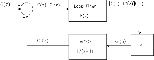
If the z transform of the VCXO integrator block is modeled as 1/(z - 1), then the z transform of the closed loop transfer function for the above loop is given as
![]()
This model in the z domain is

Note that the 10 Hz PCR arrival rate sets an upper bound on loop bandwidth. Useful loop bandwidths for this application are typically much lower than 10 Hz.